
Mechanical Fixture Project
UIUC-ME470 : Senior Design
Automated optical inspection tool
December 2022
Overview
For my Senior Design project at UIUC, I collaborated with four teammates to develop an automated visual inspection tool. The tool was designed to inspect the full surface of small components, such as PCBs, screws, and gaskets, with profiles with lengths under 3 inches. This project was sponsored by Sandia National Laboratories, as part of their ‘Senior Design Bonanza’ challenge, where several universities went head to head in delivering Sandia with the best solution. Though this project was designed for a full year design course, our course at the University of Illinois was only a semester.
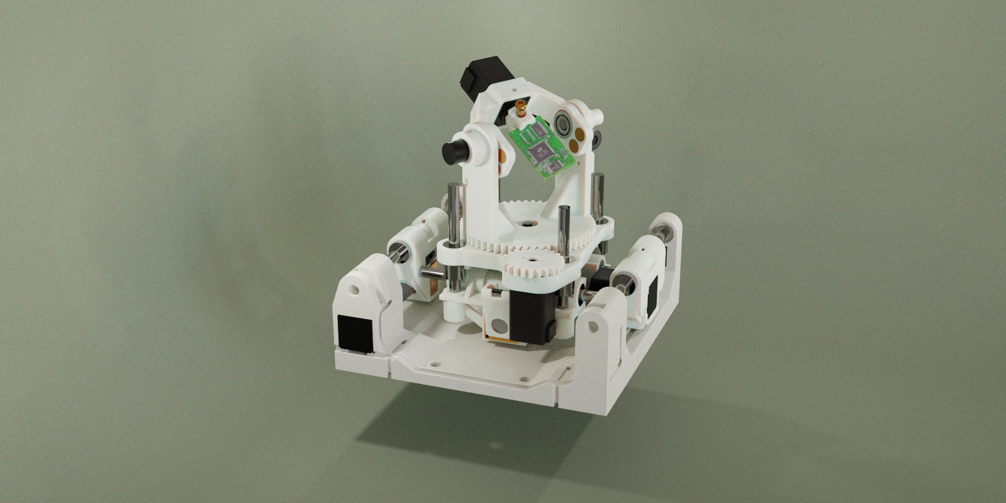
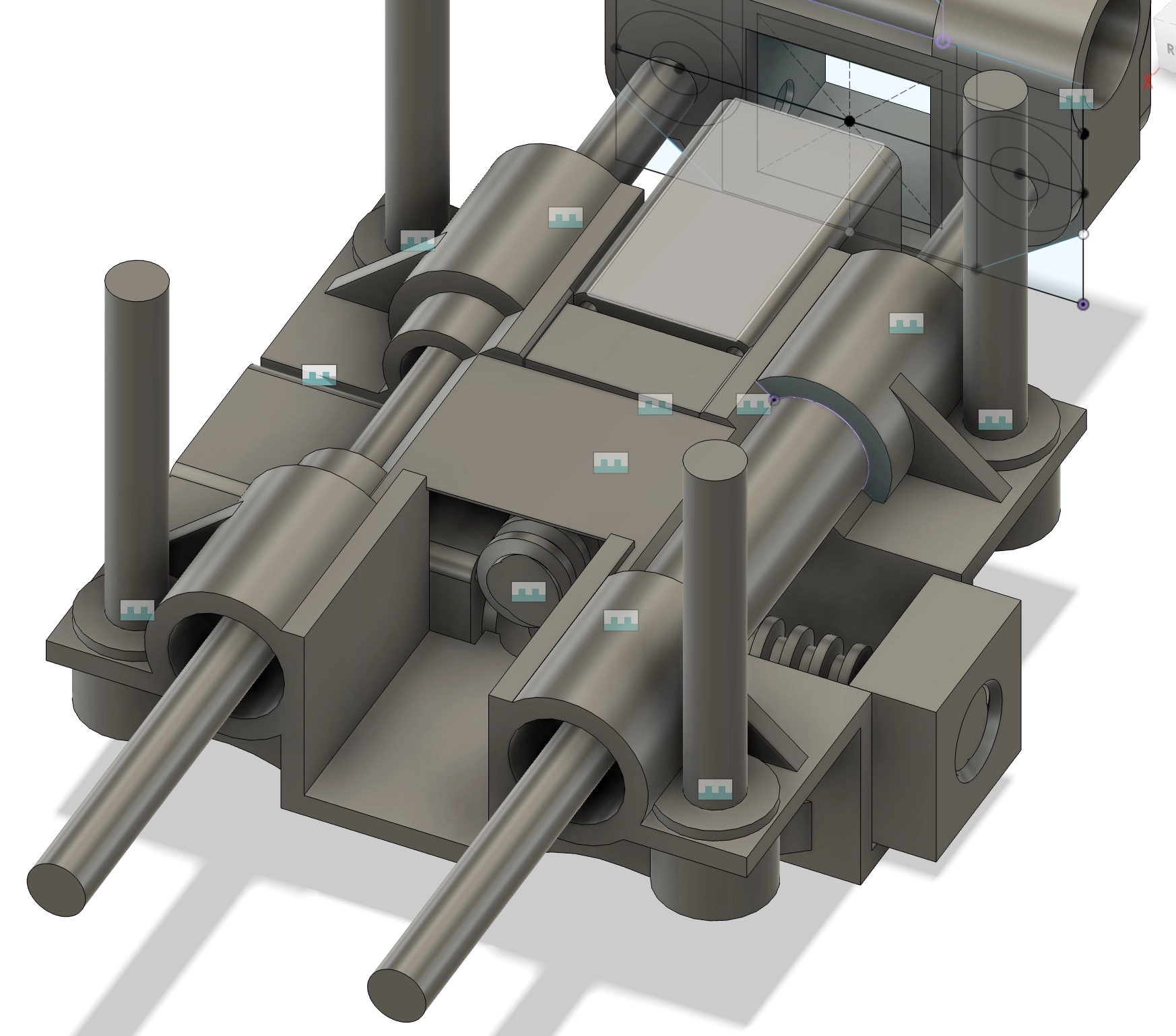
3D Render of the Fixture
Despite this, my team and I met all of Sandia’s critical goals, including many stretch goals, by tackling this complex project and promptly developing bespoke mechanical systems along with needed software. I managed the general development of the gantry, overseeing the CAD work and ensuring our team was constantly on the same page in regards to dynamic changes within the design. I also led in designing the translational subsystem and developed a piece of image planning and processing software that would allow for much broader automation capabilities. After completion, we received awards from both Sandia and from the MechSE department for our work on this project.
Design Objectives & Challenges
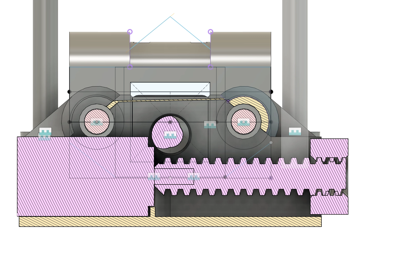
The primary challenge of this project was to build a system capable of capturing high-resolution surface images of components chosen from a predefined list, while ensuring these images can reach the component’s entire surface. This required precise control over component orientation in order to capture photos through an objective microscope. Notably, this system was constrained to fit within a cube of six inch sides. There were further stretch goals that focused on automating the inspection process and enabling the system to perform inspection on multiple objects sequentially. For more details on the project objectives and constraints see below:
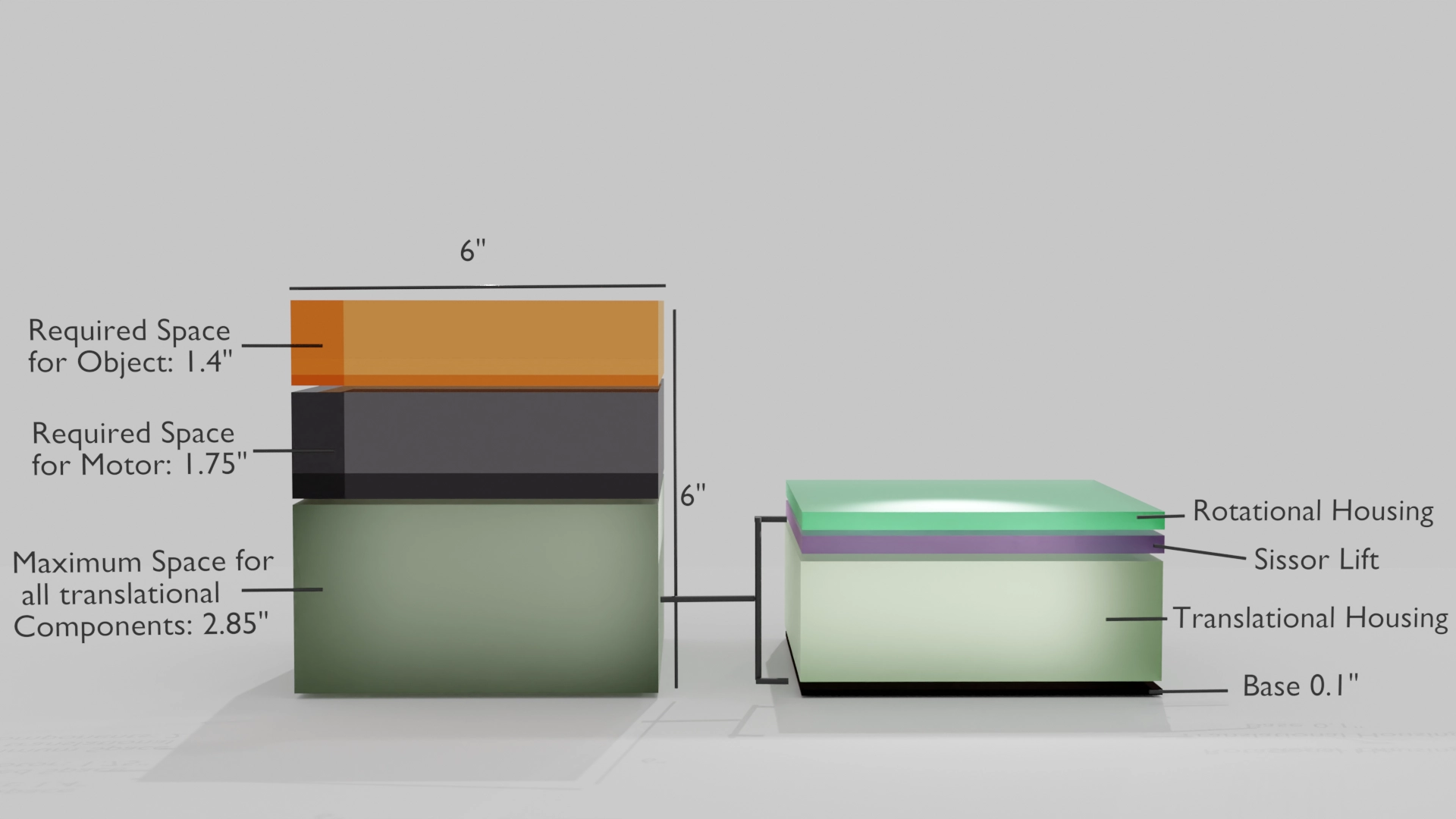
Rendering showing the strict spatial limitations of the translation subsystem [1 of 2]
System Overview
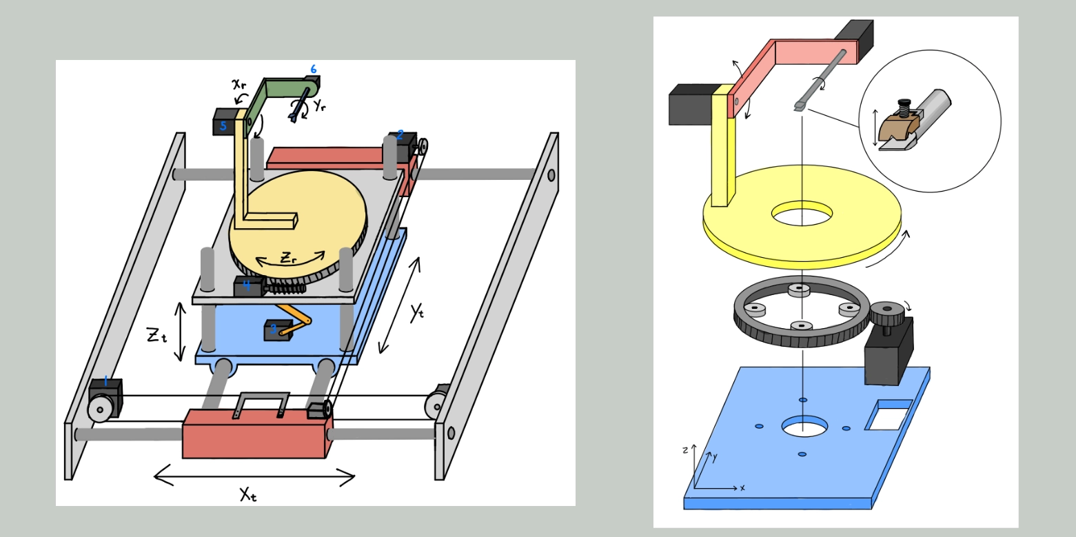
Our system used servo motors to control movement along three translational and three rotational axes, resulting in a full six degrees of freedom. I took an early interest in integrating an image-capturing system that could automatically orient components to ideal positions prior to capture, thereby ensuring full surface coverage with minimal redundancy. Though our system was not fully autonomous, this feature would be integral within a fully autonomous system.
Mechanical Design
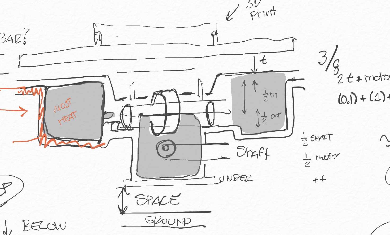
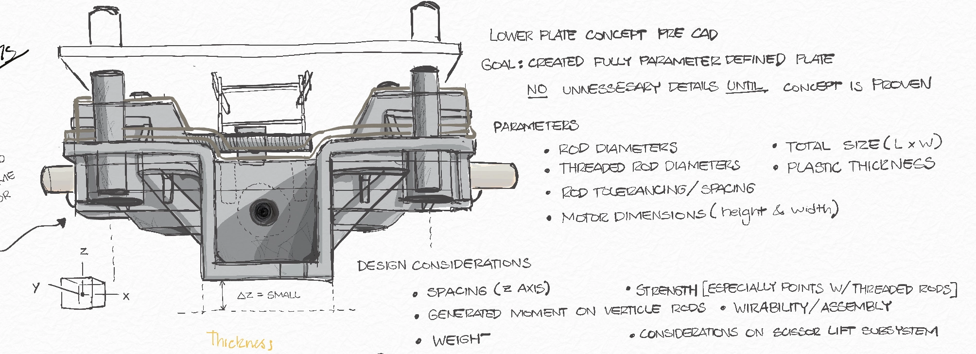
Drawings of our Design Proposal made by my team member Joel
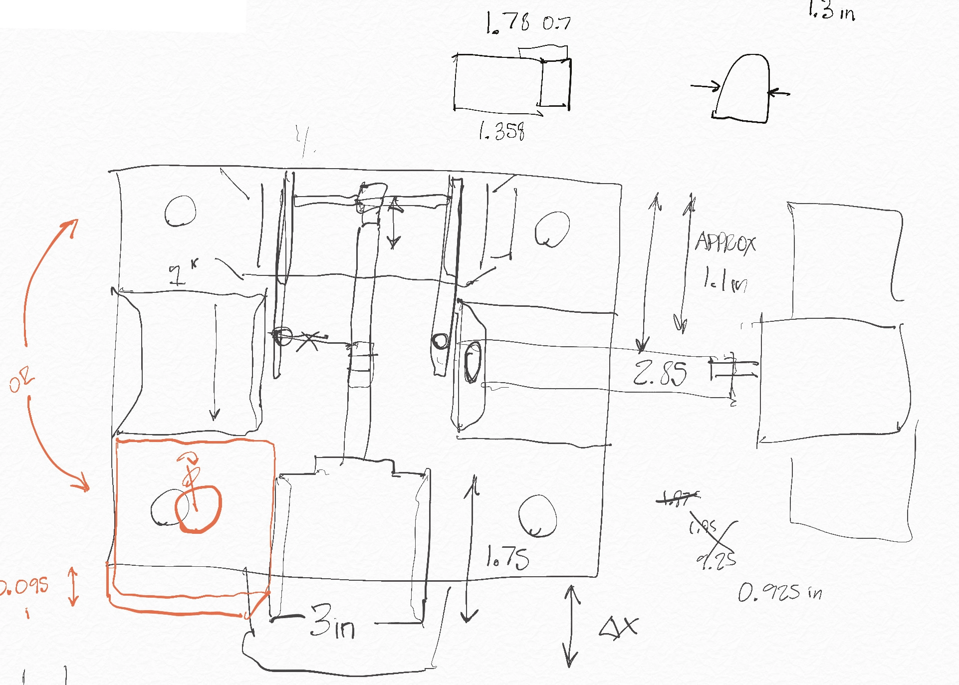
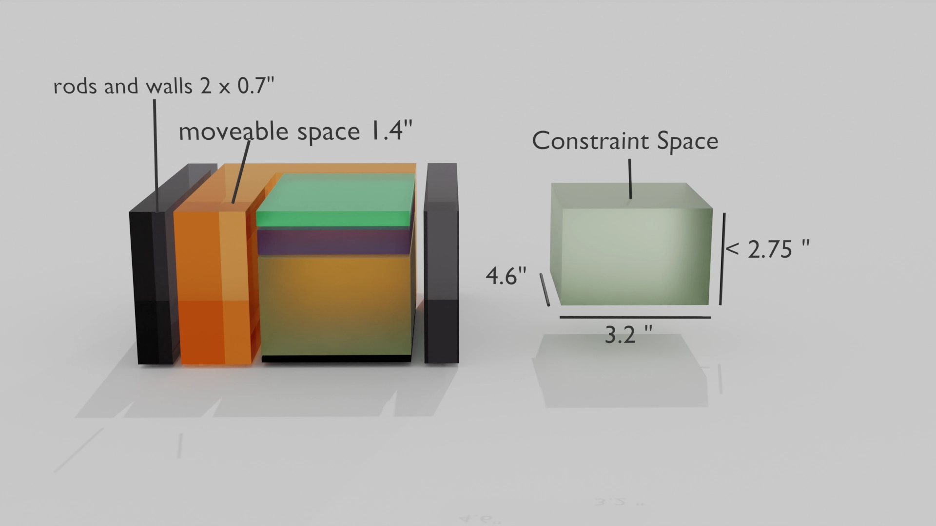
Early Drawing to Establish Constraints in the X-Y Plane
Image Processing
One of the most exciting aspects of this project for me was developing the image processing system, which I worked on during my spare time early in the semester. I wanted to create a system that could simulate the expected image quality at certain object orientations using a render engine. Then I could perform operations to choose a sufficient set of orientations to pass to the gantry. I experimented with webGL, along with some pretty bad python scripts before recalling that the open source computer graphics software, ‘Blender’ has a built-in python interpreter which I could use to control its render engine Cycles. This gave me the ability to script what I needed while taking advantage of complex internal functions like UV mapping, an isomorphic process that allows a 3D mesh to be flattened into a 2D plane for texturing purposes. I could leverage this mapping to perform operations both on 3D geometries as well as 2D planes when convenient.
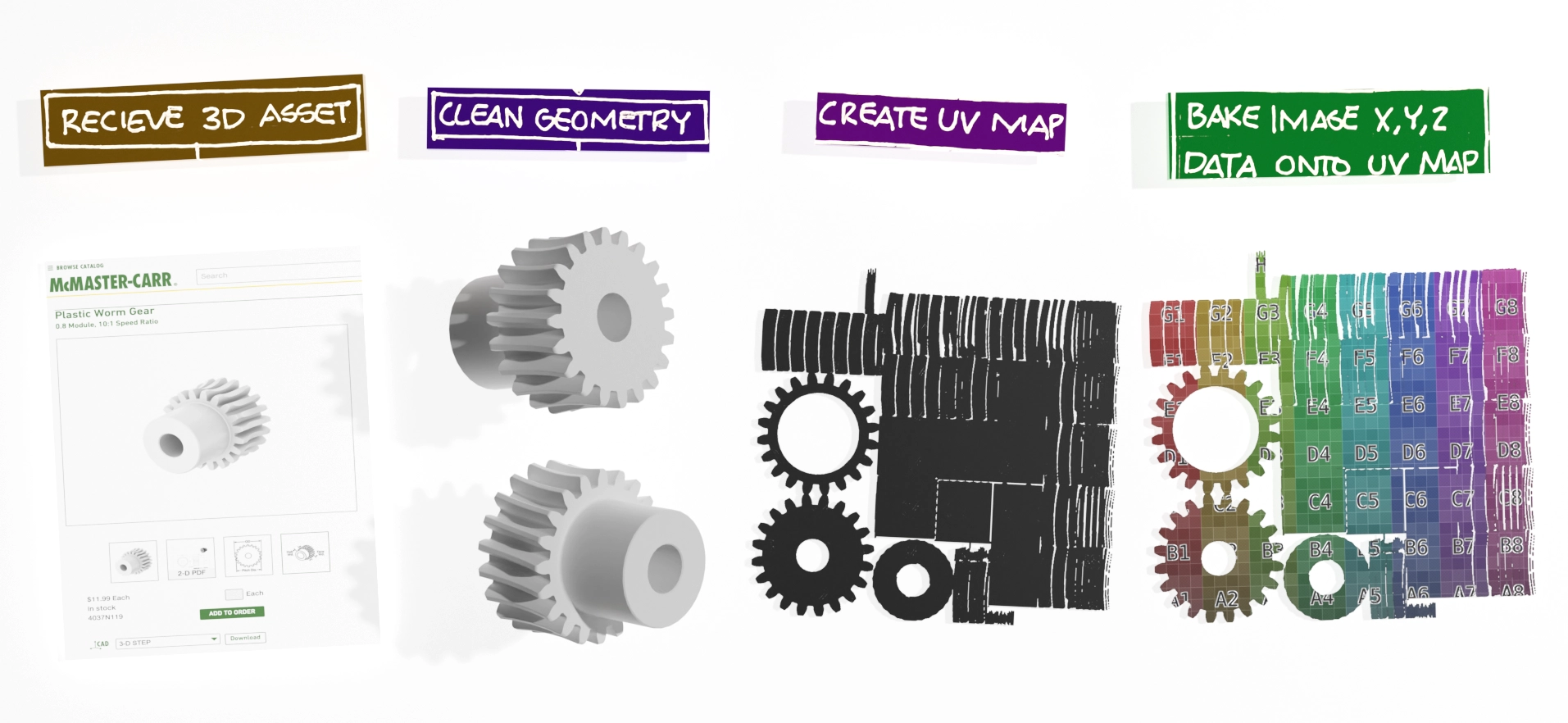
Illustration of a worm gear`s UV map
In short, the image processing workflow included:
LIST GOES HERE
The system enabled us to identify an efficient set of orientations for photographing components, maximizing the quality of the captured images while minimizing redundancy.
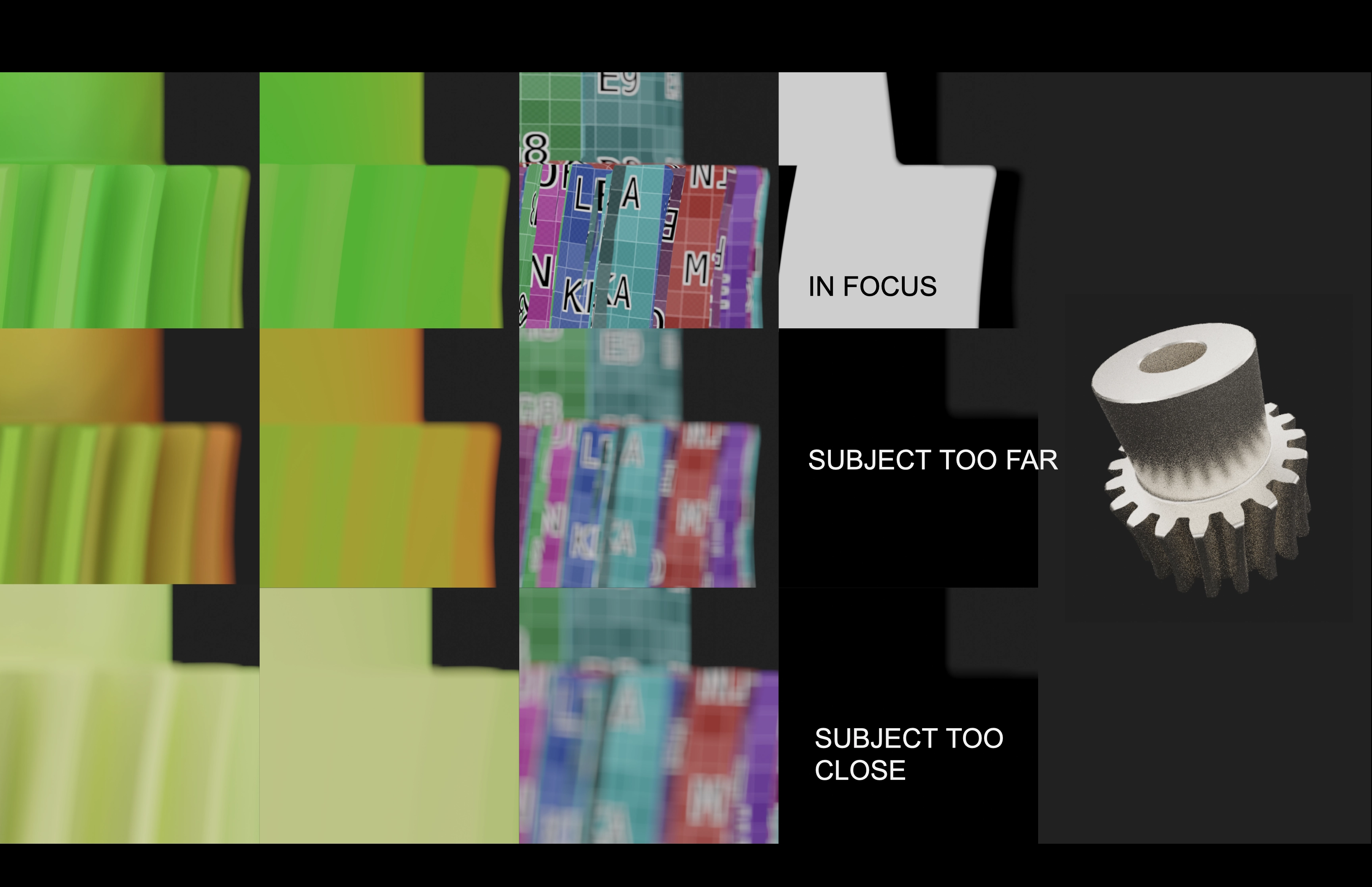
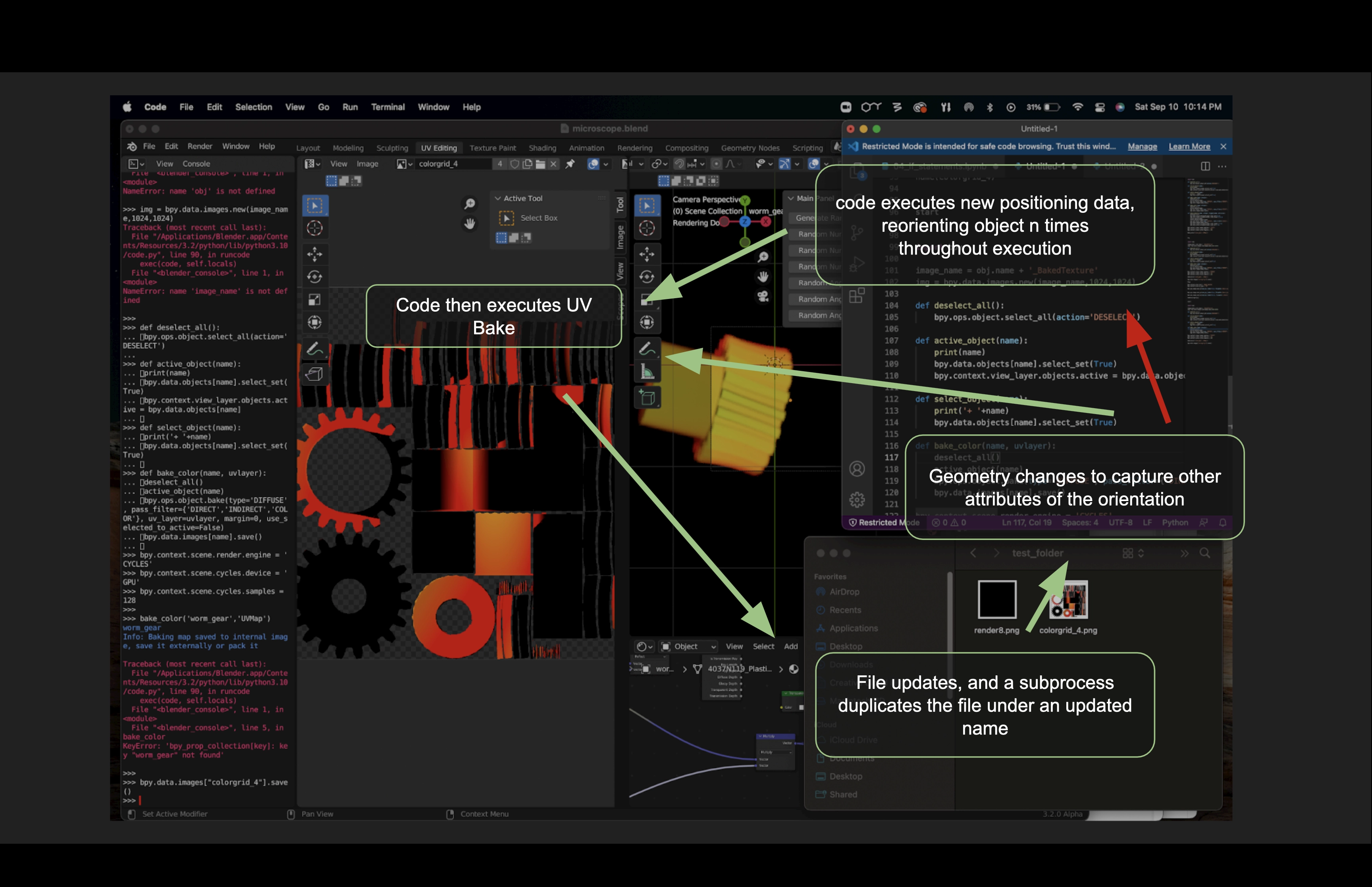
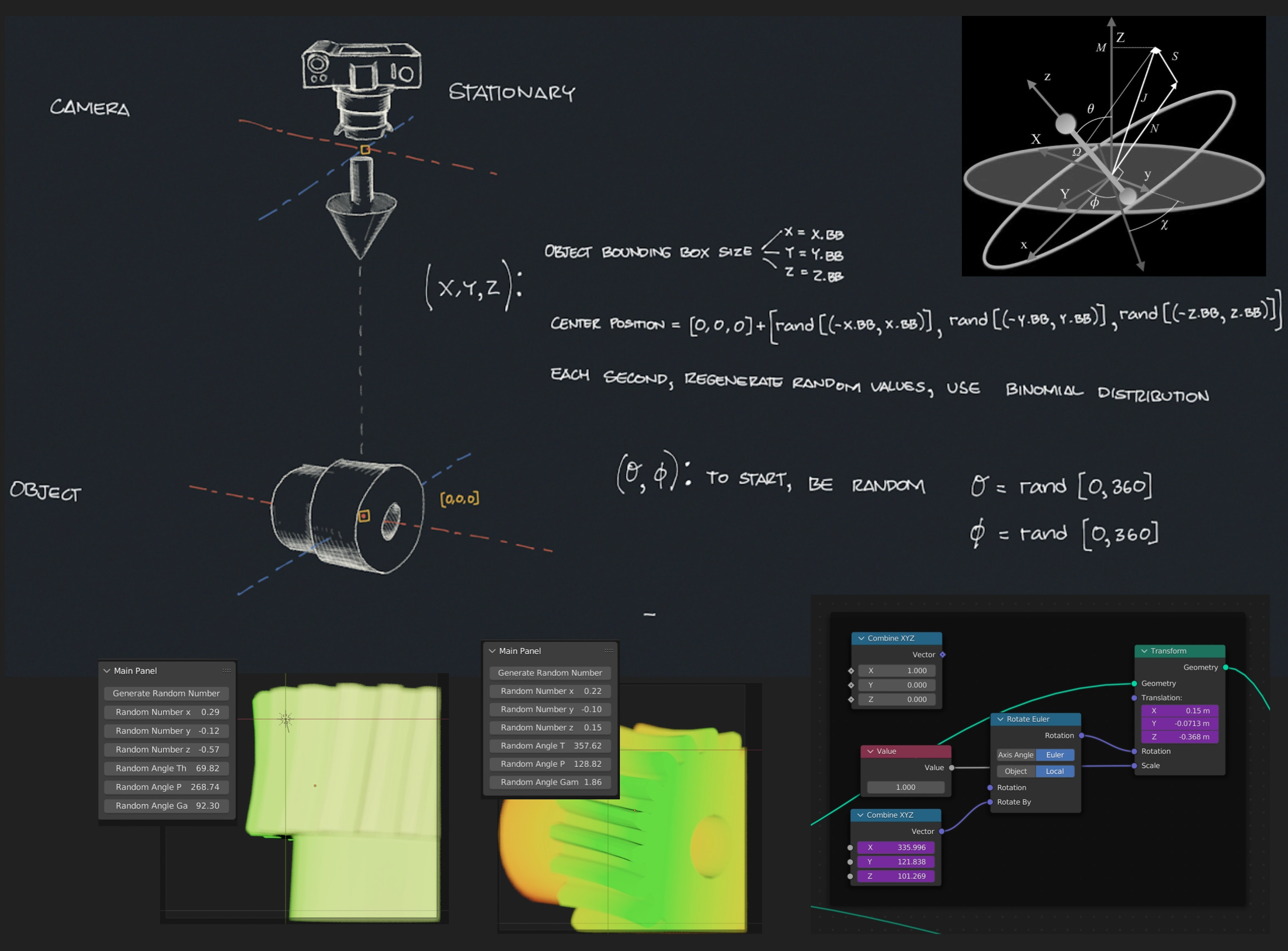
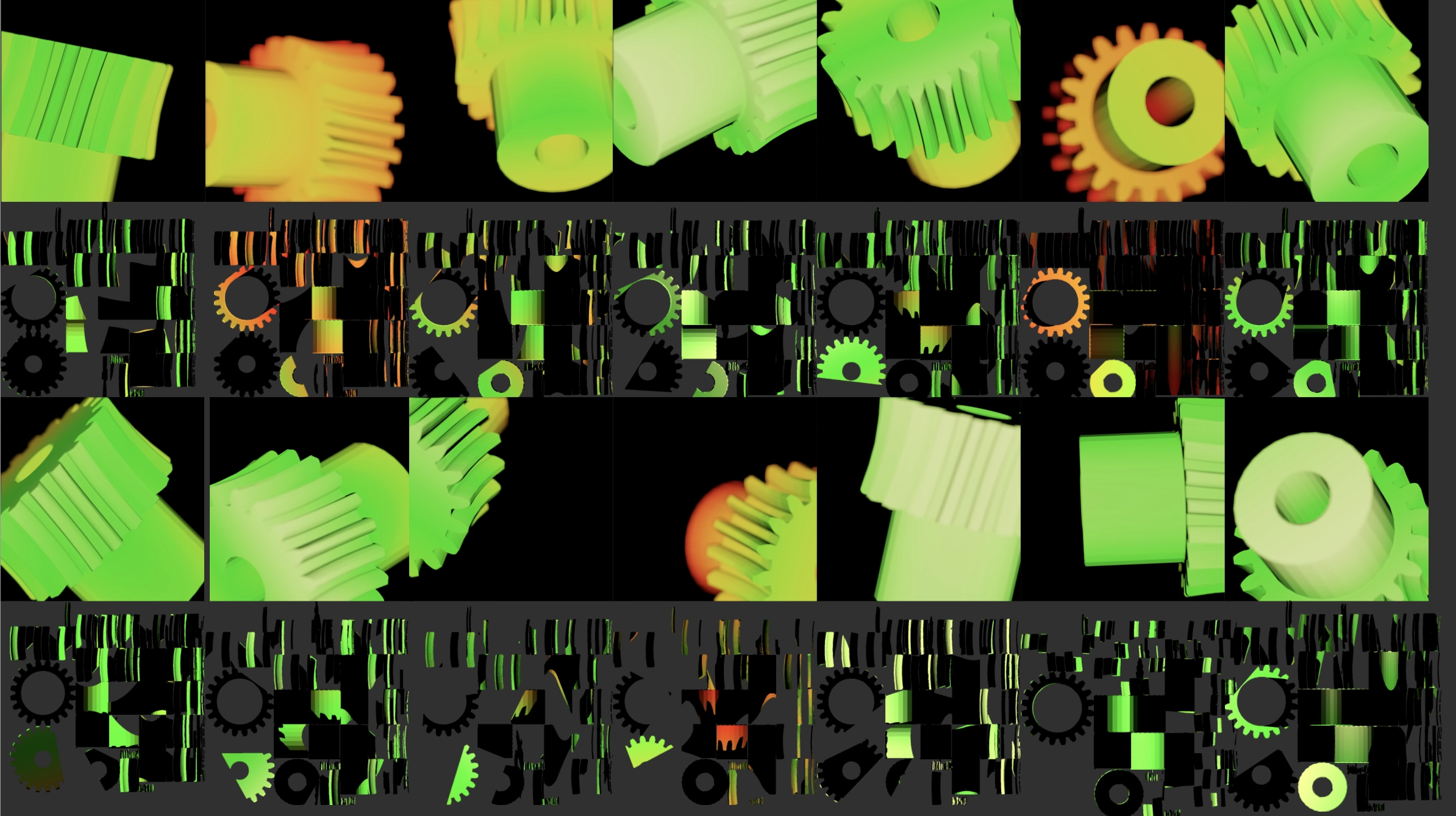
Illustration of the image quality filter`s operation
Prototype and Results
We were tasked with delivering a prototype that utilizes the advantages of additive manufacturing. Although many of our components would be fairly simple to machine, we took advantage of the complex internal geometries possible with additive manufacturing to ensure that our translational subsystem took up as little room as possible. This is mostly evident within the central hub, where internal structures are used that would prove quite challenging to machine. Our wiring system, which uses curved internal cut-outs for wires and zip ties alike, leverages 3D printing as well. While additive manufacturing makes designing parts relatively easy, these parts did impose their own challenges, largely due the availability and consistency of the printers themselves. The required tolerancing for our linear bearings to function meant that typical FDM printers in our lab would not suffice for the vast majority of our components. Only the base of the gantry was printed by an FDM printer. Of the two resin printers we could access, one was broken, and the other was improperly tuned and in extremely high demand. Due to an excess of failed prints, we fell a week behind schedule and were unable to deliver a fully functional prototype at our Trade Show. We wound up having to deal with some tolerancing and alignment issues which resulted in excess friction in our linear bearings.
To remedy this, my team and I removed one of two in series linear bearings. I also threw together a short animation demonstrating the general capabilities that we had hoped to show off during the Trade Show. The video paired with a semi-functional prototype offered an adequate demonstration of the future capabilities of our device.
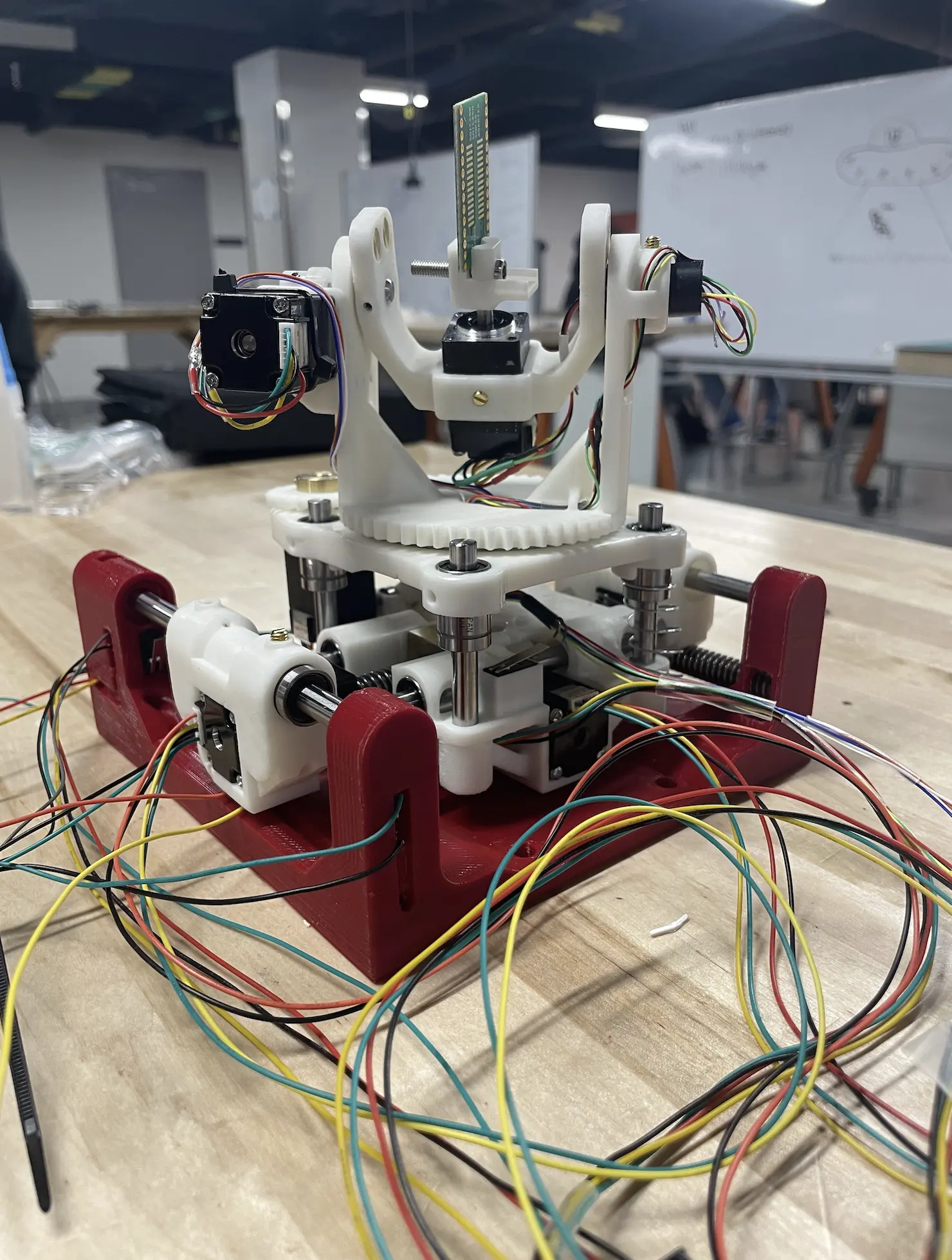
Image taken while wiring and prototyping our device
Automation
In addition to our manufacturing setbacks, due to shortages, we were unable to source our Raspberry Pi until the week before the Trade Show. Thus we focused on manual control of the gantry and never achieved the level of automation we had planned. This was quite disappointing as I viewed the prospect of automation as one of the most exciting parts of the project.
Project demo video
Trade Show & Awards
Our Trade Show exhibit was a success despite the incomplete automation capabilities. We showcased the system`s capabilities through a rendered video, a poster, and our prototype. My teammates and I took turns walking the sponsors, professors, students and friends through our challenges and approaches.
Noting that this event was long, we tried our best not to be overly regimented. We kept our discussions casual and were excited to see the enthusiasm our peers brought with their perspectives, comments, and questions.
We later received the ‘James & Loretta Bayne Award for Outstanding Senior Design Project’ from the UIUC MechSE department for having the best trade show exhibit.
The following semester, following the closure of Sandia’s ‘Senior Design Bonanza’, we received an award from Sandia for the ‘Most Comprehensive Design’. We were also proud that our project was selected to feature in Sandia’s internal newsletter.
Lessons & Possible Improvements
If I were to continue on this project, there would be a few significant improvements I would make to reduce parts, reduce cost, and improve functionality.
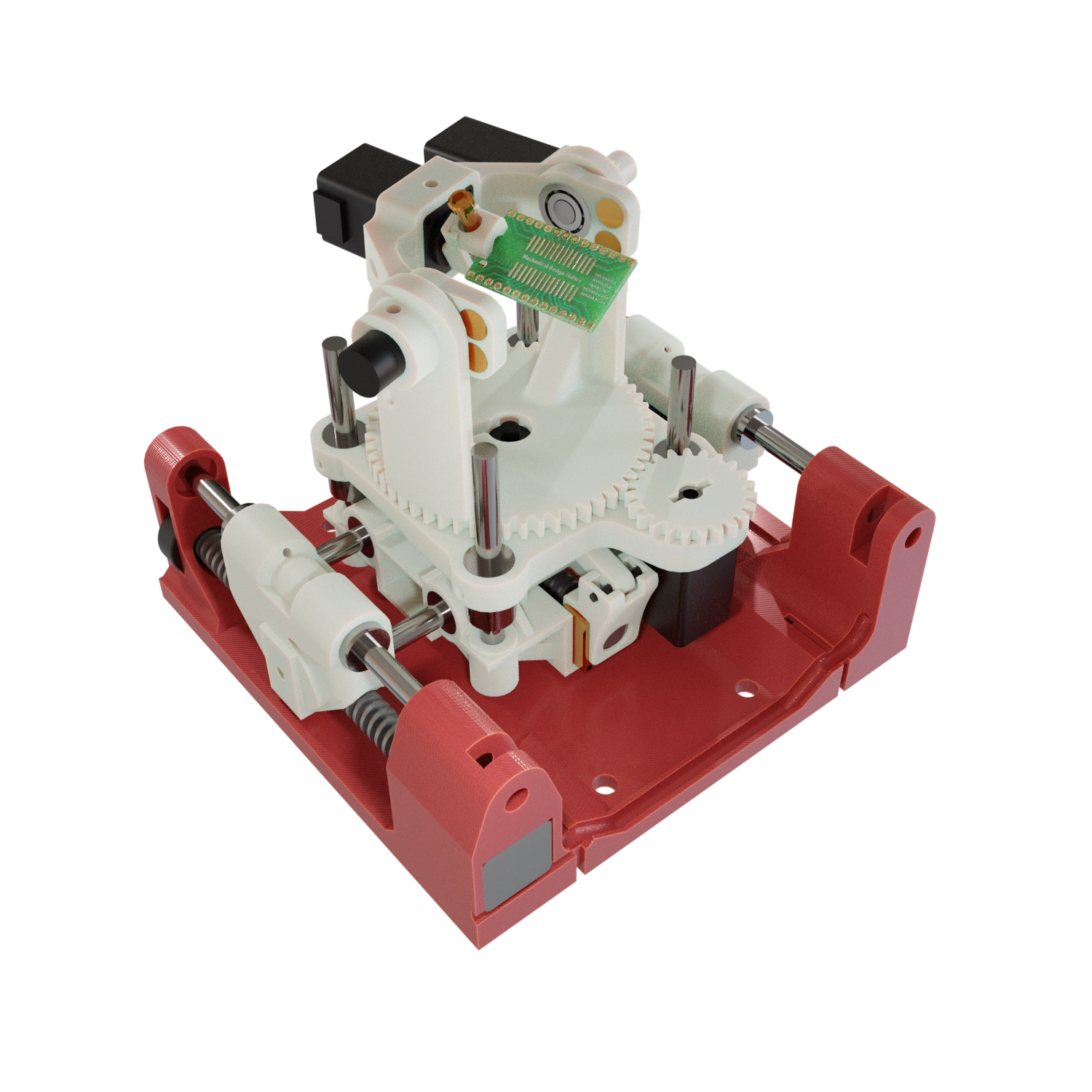
3D Render of the Fixture
I was intrigued by the idea of a spherical parallel manipulator for axial rotation. The issue is that the mechanism cannot rotate to the underside of the component. This would usually require that at some point we ‘flip’ the component around and change the pin position by 180 degrees. But this could be remedied by allowing the pin to rotate. By doing this our rotational servos would all be exerting equal force. The system would also take up less room.
I would also consider applying an evolution strategy algorithm to my image orientation selection system. Right now it’s simply selecting the best random orientations, optimizing these would allow for better quality photographs, and full surface coverage in fewer photographs, saving time, especially for scanning components with similar geometries.
I would also consider adding a controlled lighting environment to improve upon the consistency of the photographs. This would also improve the visual results of the stitched composite image and textured 3D geometry.
RESOURCES
No available resources
DOWNLOADS
No available downloads
Table of Contents
- Overview
- Design Objectives & Challenges
- System Overview
- Mechanical Design
- Image Processing
- Prototype and Results
- Automation
- Trade Show & Awards
- Lessons & Possible Improvements
RESOURCES
No available resources
DOWNLOADS
No available downloads